Maytag Washer F7 E1 Error Code: Motor Control Board Diagnosis
When your Maytag washer stops mid-cycle and displays the maytag washer error code f7 e1, the machine is telling you that the main control board and the motor control board have lost communication. This is not a user error or a simple glitch—it is a hardware-level fault that requires systematic diagnosis. For a professional technician, this code narrows the problem to a handful of components, but the actual failure point can vary significantly between models and usage conditions. This guide breaks down the F7 E1 error from a diagnostic perspective, giving you the exact tests and measurements needed to identify the failed component on the first visit.
The Communication Architecture Behind the F7 E1 Error
The F7 E1 error code falls under the “no communication” category in Maytag’s fault code system. Modern Maytag washing machines use a two-board architecture: the main control board (which handles user interface, cycle logic, and water valve control) and the motor control board (which directly drives the brushless DC motor). These two boards exchange data continuously during operation—the motor control board reports speed, direction, and current draw, while the main board sends cycle commands based on the selected program.
When the main board fails to receive a valid response from the motor control board within a specific time window—typically 2 to 5 seconds depending on the model—it triggers the F7 E1 error and halts the cycle. According to Maytag service manuals for the Bravos and MHW series, the communication protocol uses a single data line with voltage pulsing between 0V and 5V (or 0V and 12V on some models). Any interruption in this signal path—whether from a failed board, a broken wire, or a corroded connector pin—will produce the same error code.
The failure points break down into four categories, each with distinct characteristics:
- Motor control board failure: The board itself has a shorted component, a blown voltage regulator, or a failed communication chip. This accounts for the majority of F7 E1 cases.
- Wiring harness issues: A broken wire, corroded pin, or loose connector between the two boards. This is more common on machines that have been previously serviced or moved.
- Main control board failure: Less frequent, but the main board’s communication driver or power supply section can fail, starving the motor control board of power.
- Motor failure: A seized or shorted motor can back-feed voltage into the motor control board, damaging it and triggering the error.
Early Detection: Recognizing the Failure Before the Code Appears
The F7 E1 error often does not appear suddenly. Many technicians report that customers noticed intermittent issues days or weeks before the code locked the machine. Recognizing these early symptoms can help you diagnose the problem before a full failure:
- Intermittent stalling: The washer stops mid-cycle, then resumes after a few minutes without any user intervention.
- Unusual motor sounds: A humming or buzzing from the motor area without drum rotation, especially during the spin cycle.
- Cycle time drift: The timer jumps erratically, or the cycle completes far faster or slower than the selected program specifies.
- No spin or agitate: The machine fills and drains normally, but the drum never moves.
If you encounter any of these symptoms during a service call, it is worth checking the motor control board communication even if the error code has not yet appeared. Catching the problem early prevents a callback when the machine eventually locks up. For a broader reference on similar communication failures, our guide on understanding the f9e1 error code in whirlpool washers covers comparable issues in related platforms.
Systematic Diagnosis: From Simple Checks to Electrical Testing
A structured diagnostic approach prevents unnecessary part replacements and ensures you address the root cause. The following sequence moves from basic checks to advanced electrical testing.
Step 1: Visual Inspection and Power Cycle
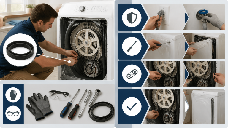
Start with the fundamentals. Unplug the washer for at least 5 minutes. This fully discharges the control board capacitors and clears the error memory. Plug it back in and run a diagnostic cycle (consult the service manual for the specific diagnostic mode on your model). If the error clears and does not return, the issue was a transient voltage spike or a software glitch. If it returns immediately, proceed with the hardware inspection.
Check for physical damage:
- Inspect the main control board for burnt components, bulging capacitors, or signs of moisture intrusion.
- Examine the motor control board, typically located at the bottom of the machine near the motor, for the same issues.
- Look at all wiring harness connectors. Are they fully seated? Are any pins pushed back, corroded, or discolored?
A common finding on machines with F7 E1 errors is a loose connector that was not fully seated during a previous repair. Reseating all connectors can sometimes resolve the issue temporarily, but if corrosion or a broken wire is present, the error will return.
Step 2: Measure Power Supply to the Motor Control Board
This is the most critical test in the diagnostic sequence. Using a digital multimeter set to DC voltage, locate the connector from the main board to the motor control board. Identify the power pins, typically labeled “VCC” and “GND” or “5V” and “GND” on the wiring diagram.
Expected reading: 5.0V DC ± 0.2V (some models use 12V DC).
- If you read 0V: The main board is not sending power. Check the main board’s power supply section—fuse, transformer, and rectifier. This points to a main board failure.
- If you read voltage but it is unstable (fluctuating between 3V and 5V): There is a short or high current draw on the motor control board. Disconnect the motor from the motor control board and re-measure. If voltage stabilizes, the motor is likely shorted. If voltage remains unstable, the motor control board is faulty.
- If you read correct voltage: The main board is supplying power. The motor control board is either not communicating or is receiving a corrupted signal. This is a classic motor control board failure.
Step 3: Check the Communication Line
Between the main board and motor control board, there is a single data line, often labeled “DATA” or “COMM” on the schematic. With the washer powered on and in diagnostic mode, measure the voltage on this line relative to ground.
Expected behavior: The voltage should pulse rapidly between 0V and 5V (or 0V and 12V) as data is transmitted. A steady 0V or steady 5V indicates a stuck communication line.
- If the line is stuck high or low: Disconnect the motor control board connector. If the line now pulses (measured at the main board connector), the motor control board is pulling the line down or up. Replace the motor control board.
- If the line remains stuck after disconnecting the motor control board: The main board’s communication driver has failed. Replace the main control board.
Step 4: Test the Motor Itself
A failing motor can damage a new motor control board, so this step is essential before installing any replacement parts. Measure the resistance between each of the motor’s three phase windings (typically labeled U, V, W). All three readings should be equal within 10%. Also check for a short between any winding and ground (motor case).
- If you find a short to ground: The motor is bad and must be replaced along with the motor control board. Installing a new motor control board on a shorted motor will destroy the new board immediately.
- If the winding readings are unequal: The motor has an internal fault. Replace both the motor and the motor control board.
Failure Mode Analysis: What the Data Shows
Field data from appliance repair forums and service bulletins provides a useful ranking of failure likelihood. While exact percentages vary by model and region, the following table reflects aggregated technician reports:
| Cause | Probability | Typical Models Affected | Repair Action |
|---|---|---|---|
| Motor Control Board Failure | 60% | Bravos XL, MHW5500, MVWB700V | Replace motor control board |
| Wiring Harness Issue | 20% | All models, especially after repairs | Repair or replace harness |
| Main Control Board Failure | 15% | Older models (2010-2015) | Replace main control board |
| Motor Failure | 5% | High-use commercial or large-family units | Replace motor and motor control board |
Note: Percentages are estimates based on aggregated technician reports and may vary by region and usage.
One interesting pattern that emerges from service data is the correlation between model age and failure type. Older Maytag machines (2010-2015) show a higher incidence of main control board failures, likely due to capacitor aging in the power supply section. Newer models (2018+) with updated board designs tend to fail more often at the motor control board, possibly because the boards run hotter due to more compact enclosure designs.
This trade-off analysis reveals an important diagnostic heuristic: if you are working on a machine manufactured before 2016, allocate more diagnostic time to the main board’s power supply section before assuming the motor control board is at fault. For machines from 2018 onward, the motor control board should be your primary suspect, especially if the wiring harness appears intact.
Pro Tips for Motor Control Board Diagnosis
This section provides actionable steps to improve diagnostic accuracy and avoid common pitfalls that lead to repeat service calls.
Tip 1: Always Check the Connector Pins First
Actionable step: Before measuring any voltages, unplug the main board and motor control board connectors. Use a magnifying glass to inspect each pin for corrosion, bent pins, or pushed-back terminals. A single bad pin can cause intermittent communication loss that is difficult to trace with a multimeter alone.
Common mistake to avoid: Replacing a board without cleaning or replacing the connectors. Corrosion on pins is a leading cause of repeat failures. Use electrical contact cleaner and a small brush to clean the pins. If the pins are discolored or pitted, replace the connector housing and terminals. This is a low-cost fix that prevents a callback.
Tip 2: Use a Known-Good Power Supply for Testing
Actionable step: If you suspect the motor control board is bad but want to be certain before ordering a replacement, apply a regulated 5V or 12V DC supply directly to the motor control board’s power input pins with the main board disconnected. If the board draws excessive current (over 1A) or gets hot immediately, it is shorted and must be replaced.
Common mistake to avoid: Assuming a board is good just because it has power. A board can have correct voltage but still have a failed communication chip. Always perform the communication line test from Step 3 to confirm the board is actually transmitting data.
Tip 3: Check for Firmware Updates and Technical Service Bulletins
Actionable step: For newer Maytag models (2020+), the motor control board may have firmware that can be updated. Check the manufacturer’s service website for any technical service bulletins (TSBs) related to the F7 E1 error. Some updates fix communication timing issues that cause false error codes.
Common mistake to avoid: Replacing a board that only needs a firmware update. This wastes time and money. Always check for TSBs before ordering parts. In some cases, Maytag has released updated boards with revised firmware that address known communication issues, so verify you are ordering the latest revision part number.
Decision Aid: Is It the Motor Control Board or the Main Board?
Use this quick checklist to decide which board to replace. If you answer “yes” to more than two items in a column, that is the likely culprit.
Motor Control Board Likely Bad:
- [ ] Voltage at motor control board connector is correct (5V or 12V).
- [ ] Communication line is stuck high or low with motor control board connected.
- [ ] Communication line pulses correctly when motor control board is disconnected.
- [ ] Motor control board shows visible damage (burnt component, bulging capacitor).
- [ ] Motor resistance readings are equal and not shorted to ground.
Main Control Board Likely Bad:
- [ ] Voltage at motor control board connector is 0V or unstable.
- [ ] Communication line is stuck high or low even with motor control board disconnected.
- [ ] Main board shows visible damage (burnt component, bulging capacitor).
- [ ] Washer had a power surge or lightning strike near the home.
- [ ] Multiple error codes appear simultaneously (e.g., F7 E1 with F5 E3 or F6 E2).
If your results fall into both columns, prioritize the main board tests first, since a main board failure can produce symptoms that mimic a motor control board failure. For additional context on related communication errors, our maytag error code f5 e3 fix guide covers a similar two-board communication failure in a different subsystem.
Frequently Asked Questions
Can I reset the F7 E1 error without replacing parts?
In most cases, no. A simple power cycle (unplugging for 5 minutes) may clear the error if it was caused by a temporary glitch. However, if the error returns immediately or after a short run, a hardware fault is present. The only exception is a loose connector; reseating all wiring harnesses can sometimes resolve the issue, but this is a temporary fix if corrosion or a broken wire is the root cause.
Is it safe to run the washer with the F7 E1 error?
No. The error indicates the motor control board is not communicating, meaning the washer cannot properly control the motor. Running the machine in this state can cause the motor to run at full speed uncontrollably or not run at all, potentially damaging the motor, belt, or drum. It is best to stop using the washer until the issue is diagnosed and repaired.
How much does it cost to replace a motor control board on a Maytag washer?
The motor control board itself typically costs between $80 and $150 for the part, depending on the model. If you hire a professional technician, expect to pay an additional $100 to $200 for labor, bringing the total to $180 to $350. This is generally cheaper than replacing the entire washer, which can cost $600 to $1,200 for a comparable model.
What is the difference between F7 E1 and F7 E2 errors?
The F7 E1 error indicates no communication between the main control board and the motor control board. The F7 E2 error typically indicates a motor speed sensor fault, where the motor control board receives no feedback from the tachometer or hall sensor. While both relate to the motor system, F7 E2 points more directly to the motor or its speed sensor rather than the communication link between boards.
Conclusion
The maytag washer error code f7 e1 is a communication failure between the main control board and the motor control board. While the motor control board is the most common culprit, a thorough diagnosis—including power supply measurement, communication line testing, and motor resistance checks—is essential to avoid misdiagnosis. By following the step-by-step guide and using the decision aid provided, you can confidently identify the failed component and perform an efficient repair.
If you are a DIY homeowner, start with the visual inspection and power cycle. If the error persists, the motor control board is the most likely replacement. For professional technicians, always check for firmware updates and connector corrosion before ordering parts. For a broader understanding of error codes, refer to our maytag washer error codes list for cross-referencing. If you encounter a similar issue on a Whirlpool machine, our guide on how to diagnose f3 e1 error in whirlpool washing machine may also be helpful.
Take action today: unplug your washer, perform the visual inspection, and measure the power supply to the motor control board. A systematic approach will save you time, money, and frustration.